Bridging the Gap between BIM and GIS
The OLS-project. How can digital building models be validated for air safety-compliance in the vicinity of airports? A UNIGIS master thesis.
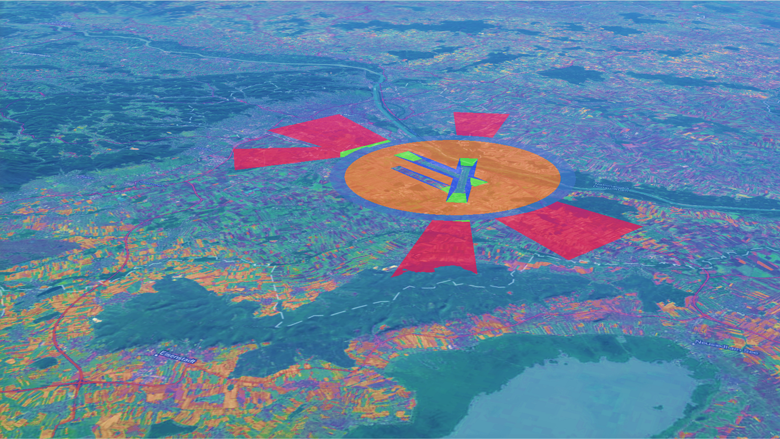
Figure 1: Model of OLS at Vienna airport
In my master thesis titled “BIM- and GIS-Integration for the semi-automatic check of architectural models against obstacle limitation surfaces at Vienna International Airport” I examined the possibilities to use IFC-models as digital building representations to be checked for compliance in a GI-environment , with national and international requirements for airspace-safety concerning obstacle-limitation.
Conventionally, building permits for constructions in the vicinity of airports are granted based on 2D drawings and a coarse approximation of defined spaces free of terrestrial obstacles. Due to the limited capability to depict 3D-phenomena on a 2D-map, the process is error-prone and time consuming. To speed up and automate this process, my thesis employs a 3D model of the restricted airspace and a transformation of the built environment from Building Information Modeling (BIM) into a GIS-format for automatic collision-detection.
As we board a plane, we naturally expect a smooth journey to our next destination, assuming a path without any obstacles. One generally thinks of the sky consisting of only air and clouds, but transitioning from one to the other during take-off and landing, an aircraft must take care to avoid terrestrial obstacles like topographic formations, trees, buildings, or technical installations such as powerlines, wind power-generators, or antennas.
ICAO, one world – one sky
To guarantee a safe approach and take-off, several international laws and regulations have been put into action and been specified since the beginning of international civil aviation in the first half of the 20th century. These regulations, provided by the International Civil Aviation Organisation (ICAO) define specific obstacle-limitation surfaces (OLS) around runways and airports that must not be penetrated by any terrestrial obstacle. OLS are defined through polygonal or conical surfaces with specific dimensions according to the available approach-process of the given airport. Particularly for international airports, approach-processes are highly automated. Aircrafts are guided by instrument landing systems (ILS) and steered by autopilot-systems on an optimised glide path towards the runway. The dimension and geographical location of the OLS correspond to these glide paths.

Figure 2: plane approaching the threshold of a runway | (Pexel: Nguyen Hung & Marina Hinic)
Regulations and law
The ICAO regulations are turned into national law to be legally binding. For EU member nations, the requirements of the European Union Aviation Safety Agency (EASA) also apply. In my case for Vienna Airport, the legal provisions of the Republic of Austria apply, which define a unique safety zone plan for each airport with regard to the OLS. The illustrations in this document are 2-dimensional coordinates with additional information on the height of the reference runway and the so-called airport reference point.
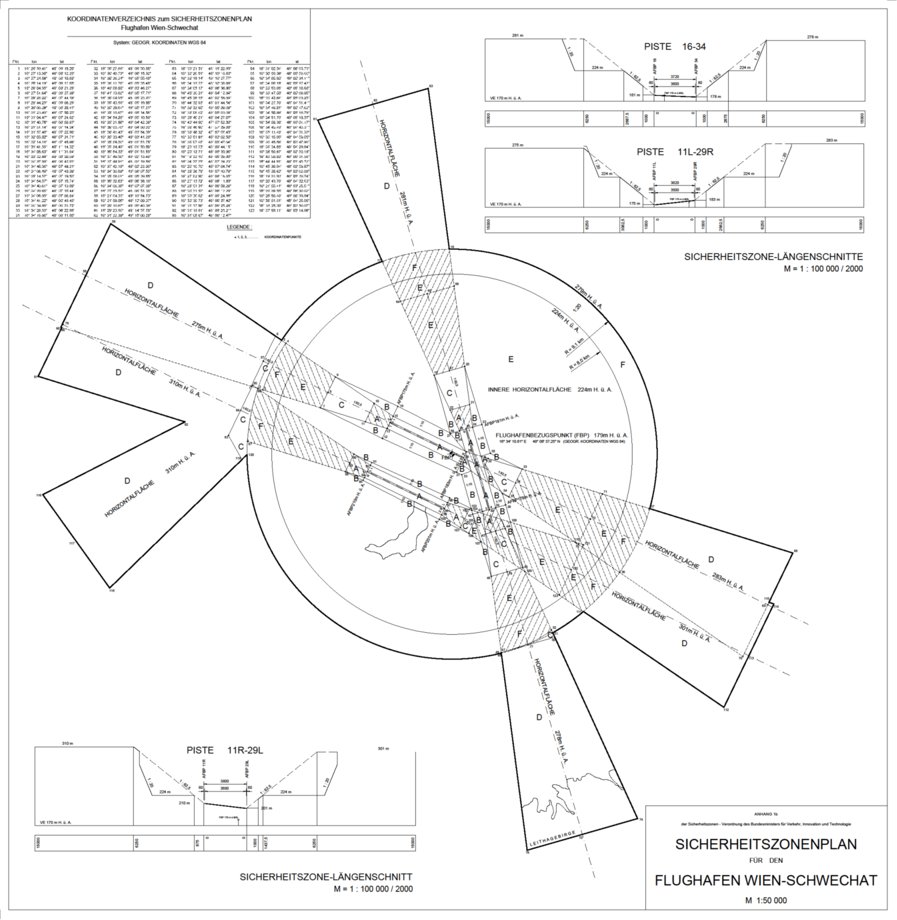
Figure 3: depiction of the safety zone plan of Vienna Airport (Sicherheitszonenverordnung-Coordinates, BMK)
The intersection of real estate growth and airspace safety considerations
In contrast, airports also need buildings and technical infrastructure. Topographical conditions may lead to a validation of the OLS, and since those spatial phenomena stretch over around 40 km, they often interfere with the interests of cities and other real-estate developments. To secure both air travel as well as urban and regional development in areas around airports, national authorities check applications of planned buildings for compliance with the ICAO-regulations. Usually, this is done based on 2Ddrawings in floor plans and sections, which show excerpts of the position and height relationships between buildings and safety zones in a time-consuming and error prone manual process.
openBIM enters the stage
To speed up this outdated process, digital building models derived from state-of-the-art Building Information Modelling (BIM) planning processes can be used as 3-dimensional representations to be checked automatically for compliance with the ICAO regulations. Internationally, there is only one format that can transport digital building models in a standardised, semantically rich, human and machine readable, neutral and open standard: The Industry Foundation Classes (IFC)-format. It is ISO certified (ISO 16739) and the core of the openBIM methodology as described in ISO 19650. IFC models are used worldwide for the whole lifecycle documentation of buildings. IFC is a file-exchange format on the one hand but a relational, object-based schema to depict buildings and infrastructure projects in depth.
One world – different perspectives
Most spatial phenomena are too complex to translate in every aspect into a single digital model. A model is by definition an abstraction of real-world phenomena. To detect or describe the correct or viable model for a given problem, it is important to ask what answers we seek to find. The GIS-community has developed a lot of models, model-languages, and definitions to describe the real-world phenomena in a comprehensible, calculable, and comparable way to help us understand what is happening where. Such models range from remote-sensing image analysis to city-models with geographic-profiling for crime-prediction or even to depicting indoor-spaces in the CityGML-model-schema. An important focus is scalability and the seamless connection of spatial phenomena by defining a continuity through topological rules.
BIM, in contrast, is and always has been the methodology to describe buildings, building parts, and to structure the planning, construction, and operational phases of an asset throughout its lifecycle. This includes the responsibility of all stakeholders within this process and their respective information requirements to fulfil their specific tasks. The focus is on objects and their placement, relation, and properties. The granularity of geometric and alphanumeric information can be as specific as the representation of a screw in a machine-part or the maintenance-retrigger of smoke-detection sensors.
Thus, within the BIM-universe, we have a limited variety of use cases, that all deal with the building, the real estate, or the infrastructure-project, its planning, construction, operation, or administration. Even though both, the GIS-models as well as the BIM-models are an abstraction of the real world, their aim is different, their languages differ, and their focus and methodology differ.

Figure 4: the possible granularity of geometric and alphanumeric information for a screen in a BIM-model
How to bridge the gap between BIM and GIS?
Building models in the BIM-environment are always created and managed in a local and cartesian coordinate-system with a detailed description of buildings, building-equipment, and materials. While the granularity of the semantics may include the surface-colour and manufacturer of the paint to be used or the geometric depiction of a single screw, the context and environment of a building are seldom considered and described.
To take a BIM-model into a GI-environment, it is necessary to transform the file into an adequate format, and to reduce the model to the relevant parts – mainly the exterior surface of the building. Only this “shell” needs to be checked for compliance with the OLS.
From 2D to 3D
To create a 3-dimensional model of the OLS, I converted the coordinates given in the Austrian safety-zones document for the Airport of Vienna into a 3-dimensional model using the parametric modelling-software Rhino-Grasshopper. With the resulting model being stored as an IFC-File and imported into ArcGIS Pro, the first part of my checking-tool was ready.

Figure 5: the grasshopper-sript creating the 3D-model of the OLS
Height matters
One of the most crucial tasks for the endeavour to check building models for compliance with the OLS is to correctly define the relevant height-reference system. But the term “height” is relative. Height can be defined as the distance of a point in relation to a reference surface. Hence, it is important to know which reference surface the selected height refers to and how the distance is measured. Reference systems may be ellipsoid-related or gravity-related. Ellipsoid-related reference-systems are typical for GNSS. In the field of construction, height is normally defined as gravity related. The respective regulation for airspace safety at Vienna Airport states height specifications given in a gravity-based reference system in relation to the mean sea-level of the Adriatic Sea (Höhe über Adria – ü.A.) with meters as units. Those physical heights differ at each given location, since they use a quasi-geoid as reference surface which depends on the topographical conditions in the area of interest. To depict those local heights in a global context like the ArcGIS Online Scene-Viewer, with a ellipsoid-based reference-system based on the WGS84-ellipsoid, they need to be transformed twice: In the first step into a geoid-based system (orthometric height) and then into the final ellipsoid-based system.
For further information find a link to the BEV-documentation about height-systems in Austria (German version only). (BEV-Höhenreferenz-Systeme, URL: https://www.bev.gv.at/dam/jcr:bc04f1f3-40ca-4da6-80e8-da038f1c653b/Hoehenreferenzsysteme_2020.pdf, date of download: 17.02.2024)
What does LOIN stand for?
In an openBIM process, information is created and handed over to the information receiver by definitions of the requirements in accordance to the use case, project phase, actor, and data-granularity. This definition is called “Level of Information Need” (LOIN). To automate this process, it is crucial to define exactly what and how information must be submitted for the validation to work. In the given procedure, the requirements can be reduced to the separation between internal and external entities. The IFC-Schema offers a Boolean property called IsExternal that can be set to true or false for each instance of an object or object-type. For the automatic transformation, it is also necessary to define the respective coordinate-reference system that the local, cartesian reference system can be mapped to. The IFC-Schema has been fitted with two class-objects to transport this information – IfcMapConversion und IfcProjecteCRS.
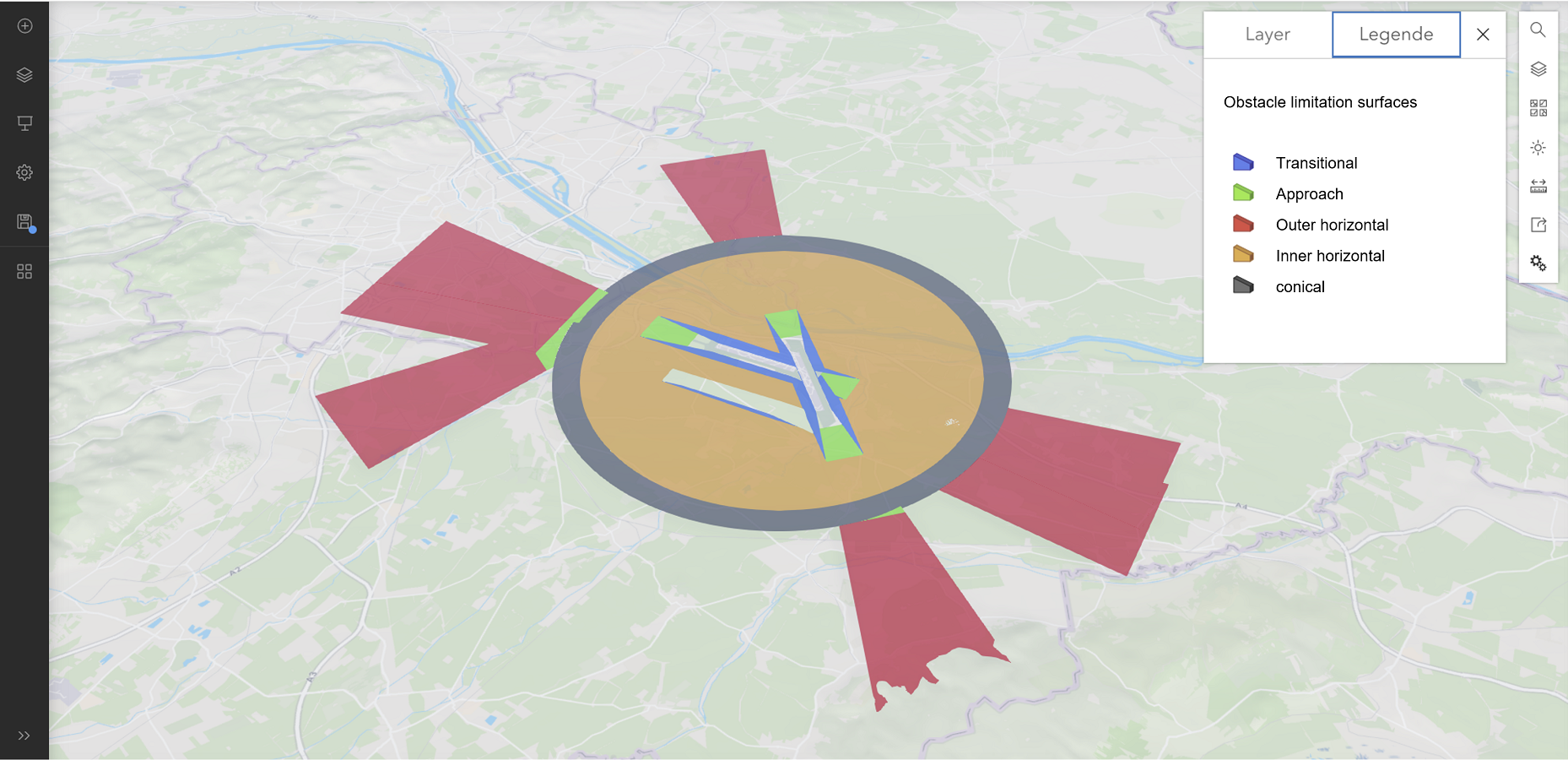
Figure 6: defining properties according to the LOIN and for georeferencing of the BIM-model
Integrating BIM and GIS
ArcGIS Pro interprets the data and writes the resulting entities into a shapefile with a multipatch geometry. With the geoprocessing-tool “Import BIM”, the elements are grouped into specific domains and can be exported into building-scene layers. With the import of the test-building, the second part of the checking-routine is available: the applicant-model in a GI-environment.
An automatic validation-tool
Combining several 3D-Analyst-Tools in the ArcGIS Pro model-builder, I created an automatic workflow to check collisions of the applicant-model with the OLS-model. The results are visualised and attributed accordingly and published in ArcGIS Online as a means of communication with the authorities. Checking-routines are simple geometric Boolean operations concatenated into a federated process. It has yet to be implemented into an automatic, end-user driven process controlled through a simple UI in a web-browser and executed on a server.
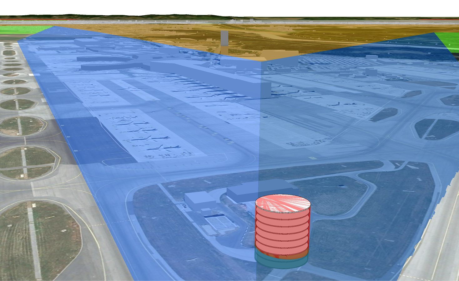
Figure 8: the imported BIM-model penetrating the OLS-model

Figure 9: dividing permitted and restricted part of the building
Data is beautiful, but it needs to be visualised for humans to understand it. So, in a last step, I needed to publish the results into a simple, intuitively, and easy to use environment that serves as a communication platform between the applicant and the administration. This is where ArcGIS Online can show its strength, with a fast and smooth depiction of even massive, data-intense models and large-scale environments. The integrated building-explorer allows importing complete architectural models for a closer inspection where necessary for authorization of exceptions.
Conclusions
The process of an automatic model-validation and the transformation between BIM and GIS is technically solved. Hardware and software can handle the amount of data. The respective standards and data models are well defined. The processes are technically feasible. Yet, there are two main issues to consider:
- Will digital models be accepted as legal matter? This is a social and political question. A main topic is the transparency and objectivity that can be considered as advantage by some and as disadvantage by others.
- Should administrative decisions be executed with proprietary software? The whole process could and should be tested and executed in an open and free software-environment to stay independent and neutral.
In conclusion, it is obvious that the implementation of the new procedure will enhance the decision-making process at Vienna Airport and speed up the administrative processes, freeing those responsible from error-prone and time-consuming manual labour.
UNIGIS Master Thesis
You want to take a look at more of the UNIGIS students’ Master Thesis? Read the blog entry from Torge Brunhorn on Remote Sensing in War Zones or browse through the Master Thesis database: Master theses in German, Master thesis in English.
>> Here you can read the full Master Thesis by Jan Morten Loës.
About the author: DI Jan Morten Loës (UNIGIS Master graduate)

Morten Loës studied architecture and worked as an architect and project-developer from 2008 to 2022. Morten shifted his focus towards the digital depiction of the built asset and now works as head of research and development at the VIE Build Company – a spin-off of Vienna International Airport. As part of his work, he is involved with the openBIM community of buildingSMART. Morten studied GIS at the UNIGIS MSc course in Salzburg from 2021 through 2023.”
References:
All figures © by Jan Morten Loës 2024, except:
Figure 2: Nguyen Hung, URL: https://www.pexels.com/de-de/foto/flughafen-runway-transport-landung-11150272/ , download-datum: 17.02.2024
Figure 2: Marina Hinic, URL: https://www.pexels.com/de-de/foto/schwarz-mehrfarbiges-bedienfeld-lot-726233/, download-date: 17.02.2024
Figure 3: BMK, URL: https://www.bmk.gv.at/dam/jcr:b6d876c5-a553-477c-a8b3-f119cedbac17/sizo_plan_wien_koordinaten.pdf, download-date: 20.02.2024


